Base Bracket: Extrude Boss & Through-All Cut
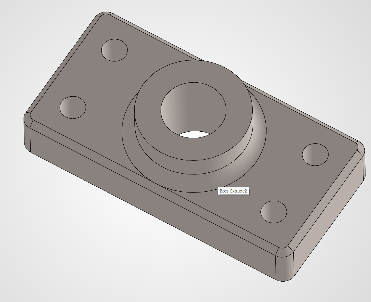
My first solid model in the course: sketch a profile on the Front plane, extrude it into a blind-depth solid, then sketch and cut a through-hole on a derived face. Simple geometry, but it's the exercise that establishes the core habit the rest of the course builds on — plan the sketch plane and the feature order before touching the mouse, rather than fixing it after the fact.
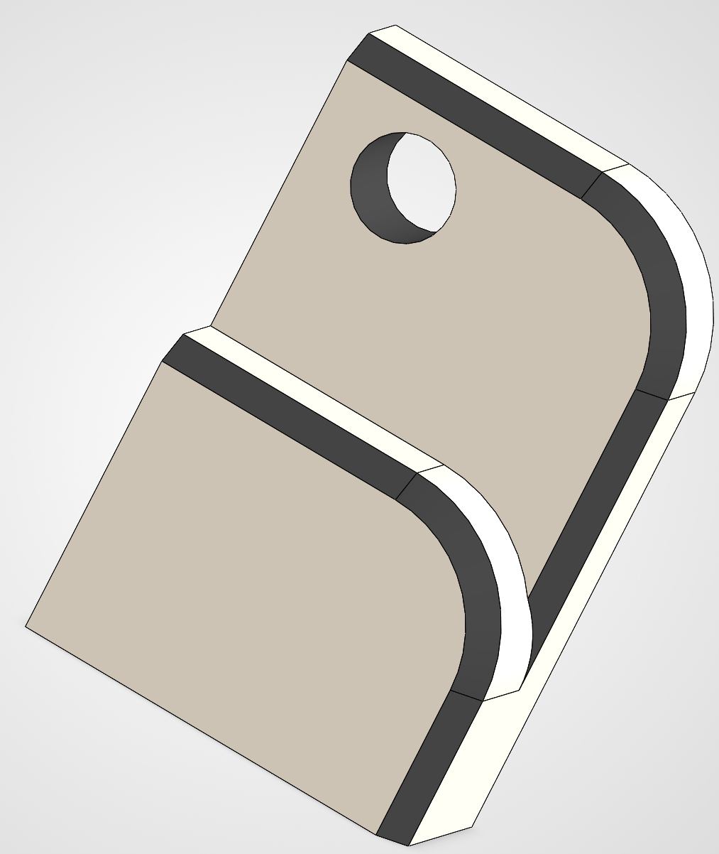
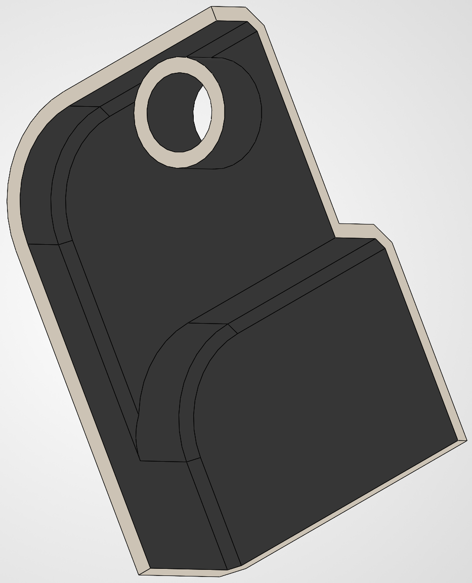
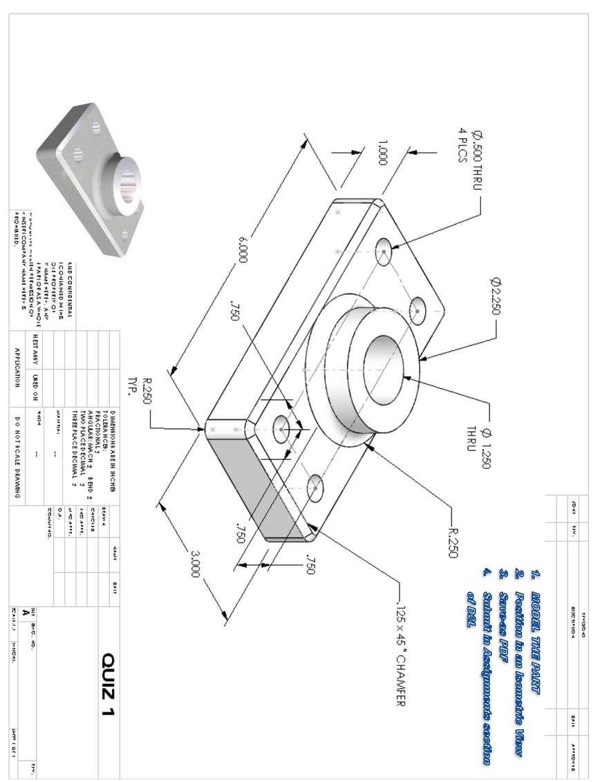
Mounting Flange: Modeled Cold From a Fully-Toleranced Print
A graded, timed modeling quiz: no step-by-step instructions, just a dimensioned print of a square mounting flange — a central bore, a 4-hole bolt pattern on a specified bolt-circle diameter, corner fillets, and a 45° chamfer callout — and I had to plan the entire feature tree myself and reproduce the part to the stated dimensions.
Drafted Housing: Section Views, Draft Angles & a Personal Rebrand
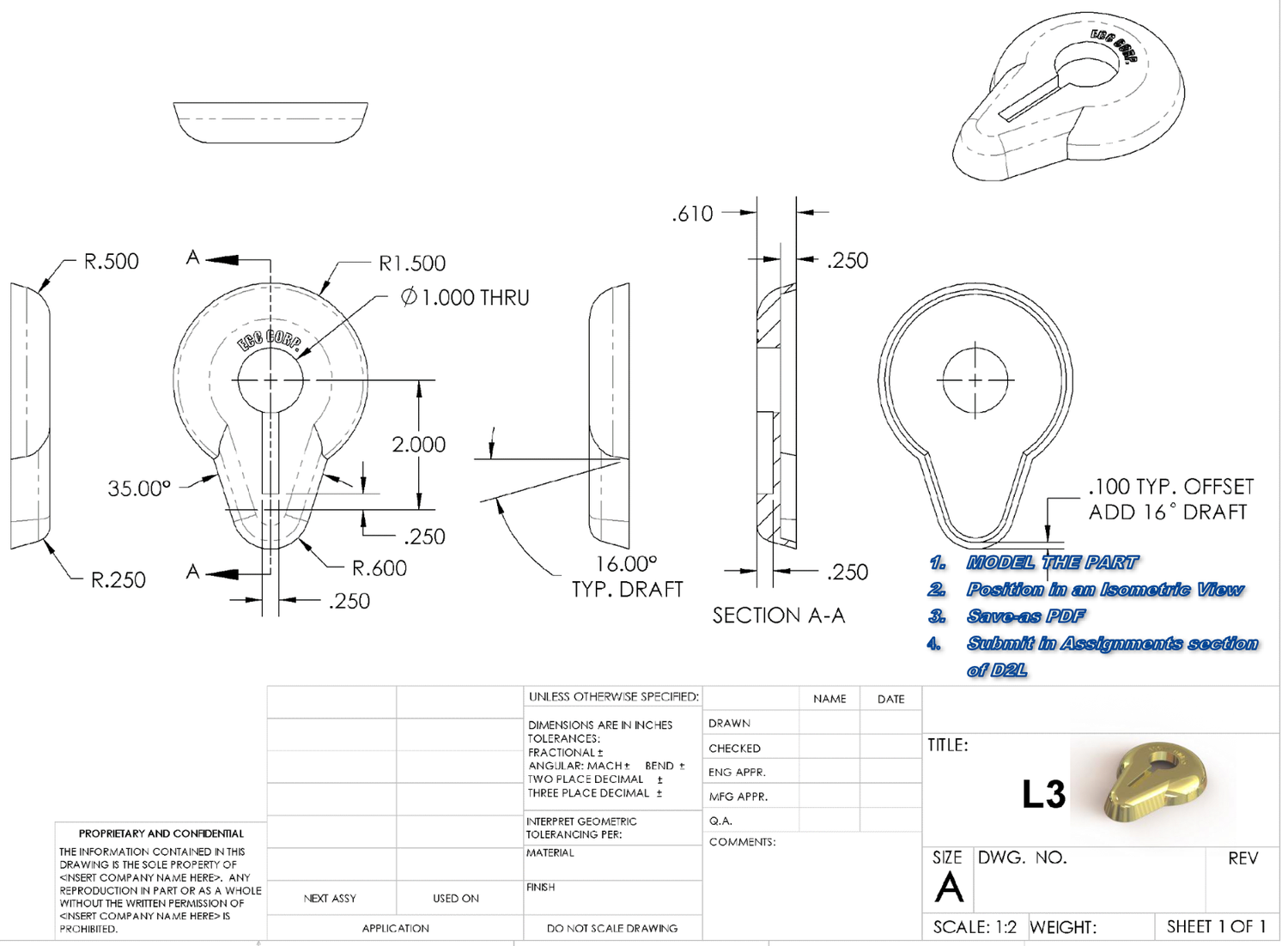
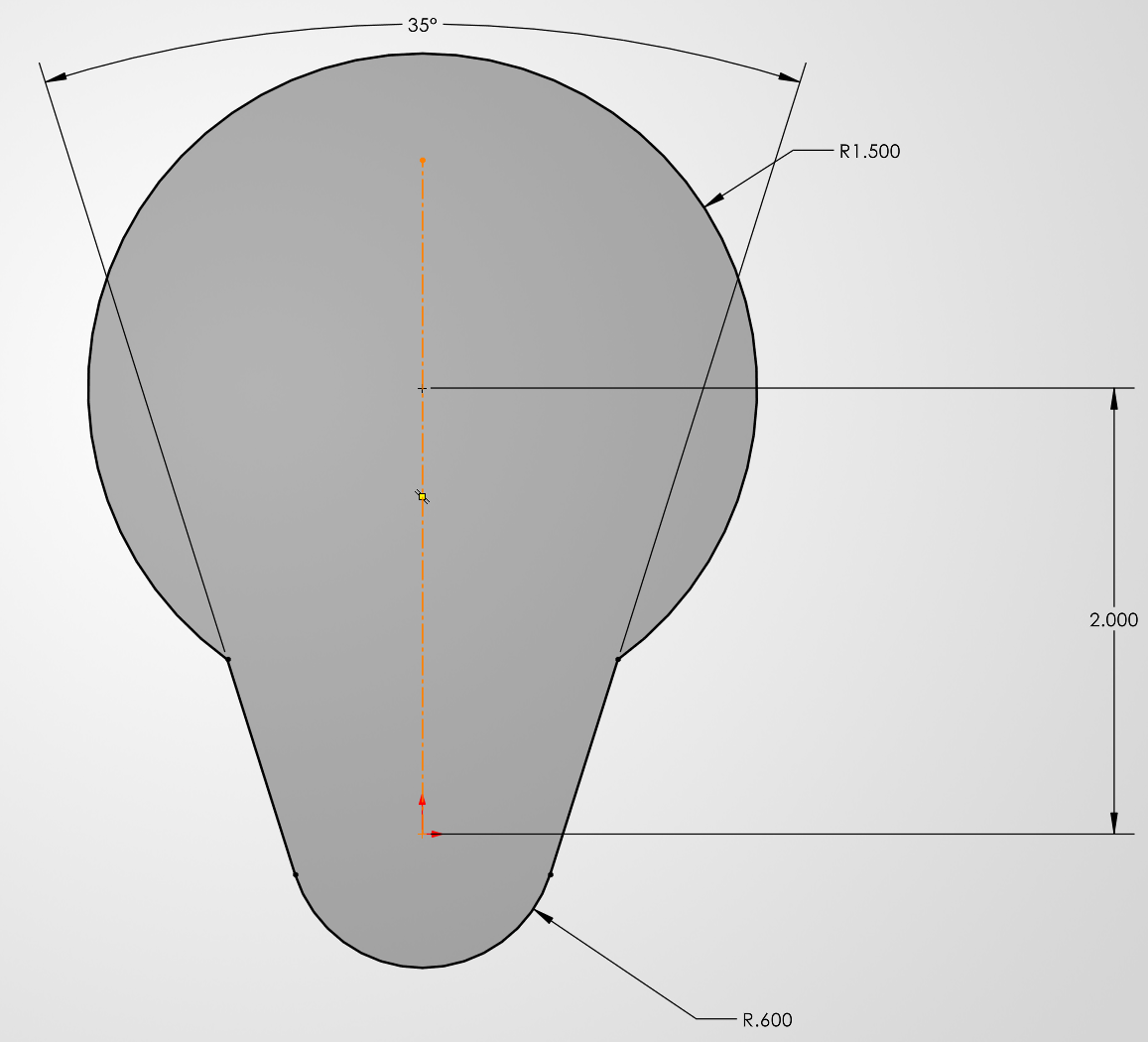
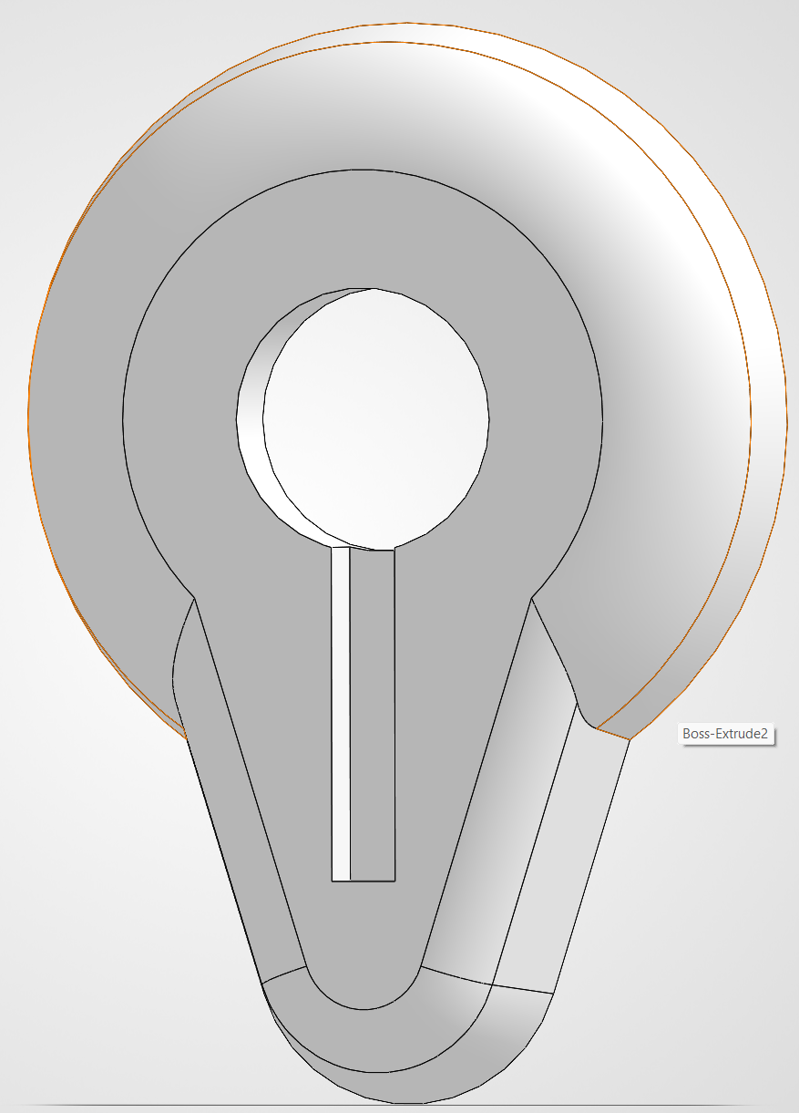
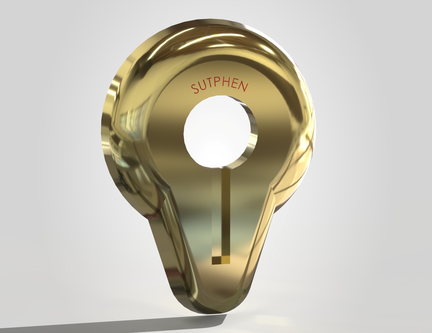
Another independent lab: build the part shown on the print, which calls out a 16° typical draft angle on the boss, a 35° included angle on the outer profile, and a section view (A-A) defining wall thickness that isn't visible from the isometric view alone. Once the model was done, I swapped the drawing's placeholder "ECC Corp" callout for "SUTPHEN" and rendered it in gold — a nod to the emergency vehicles I get to see daily at work.
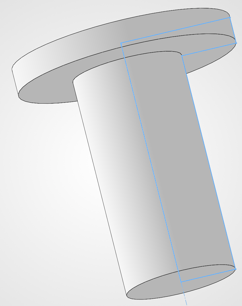
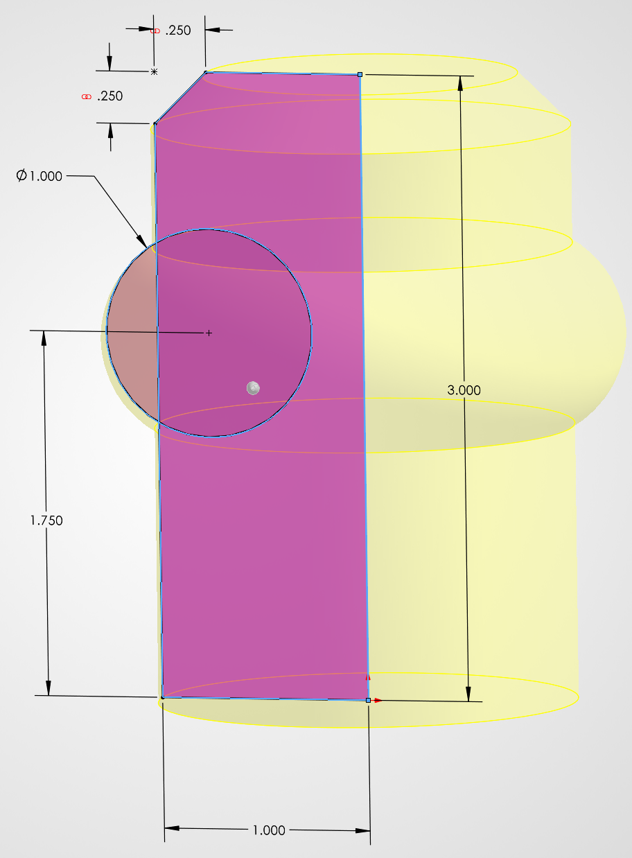
Flanged Bushing: Revolve From a Hatched Section View
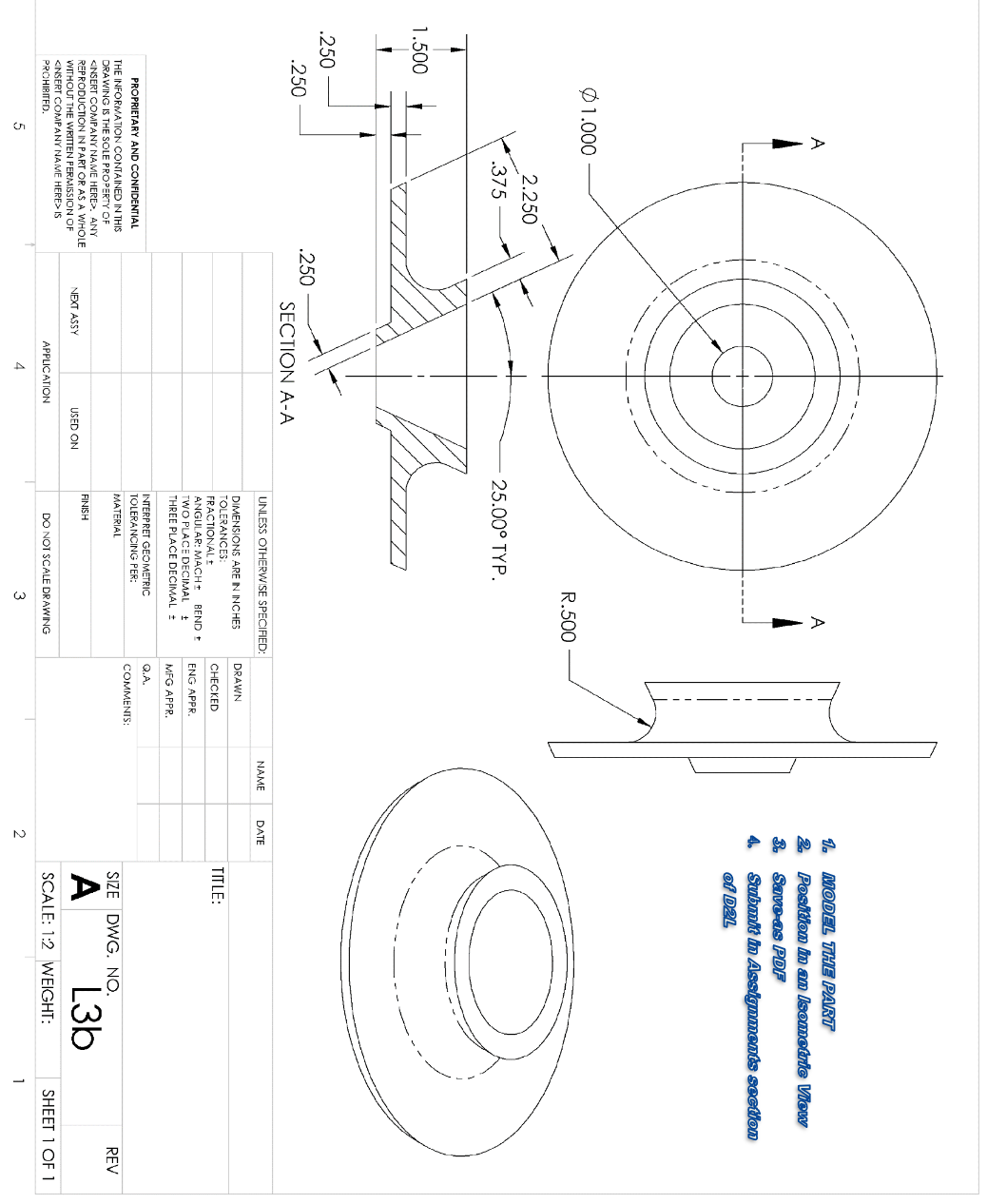
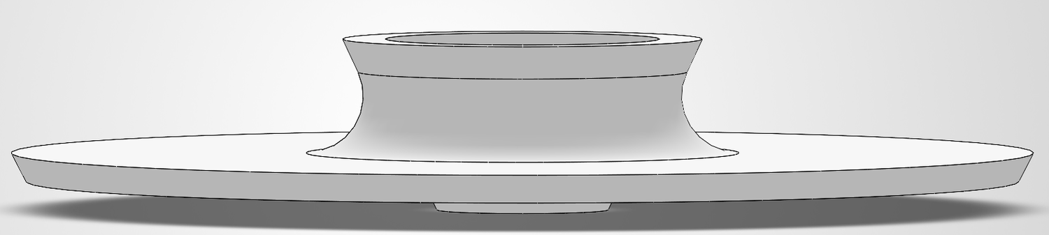
This print gives only a front view, a section view (with hatching showing the cut material), and a hidden-line isometric — no single view shows the full profile. I had to combine the section's wall-thickness dimensions with the .500" corner radius and the 25° typical angle to build one accurate revolve profile, then revolve it 360° around the centerline.
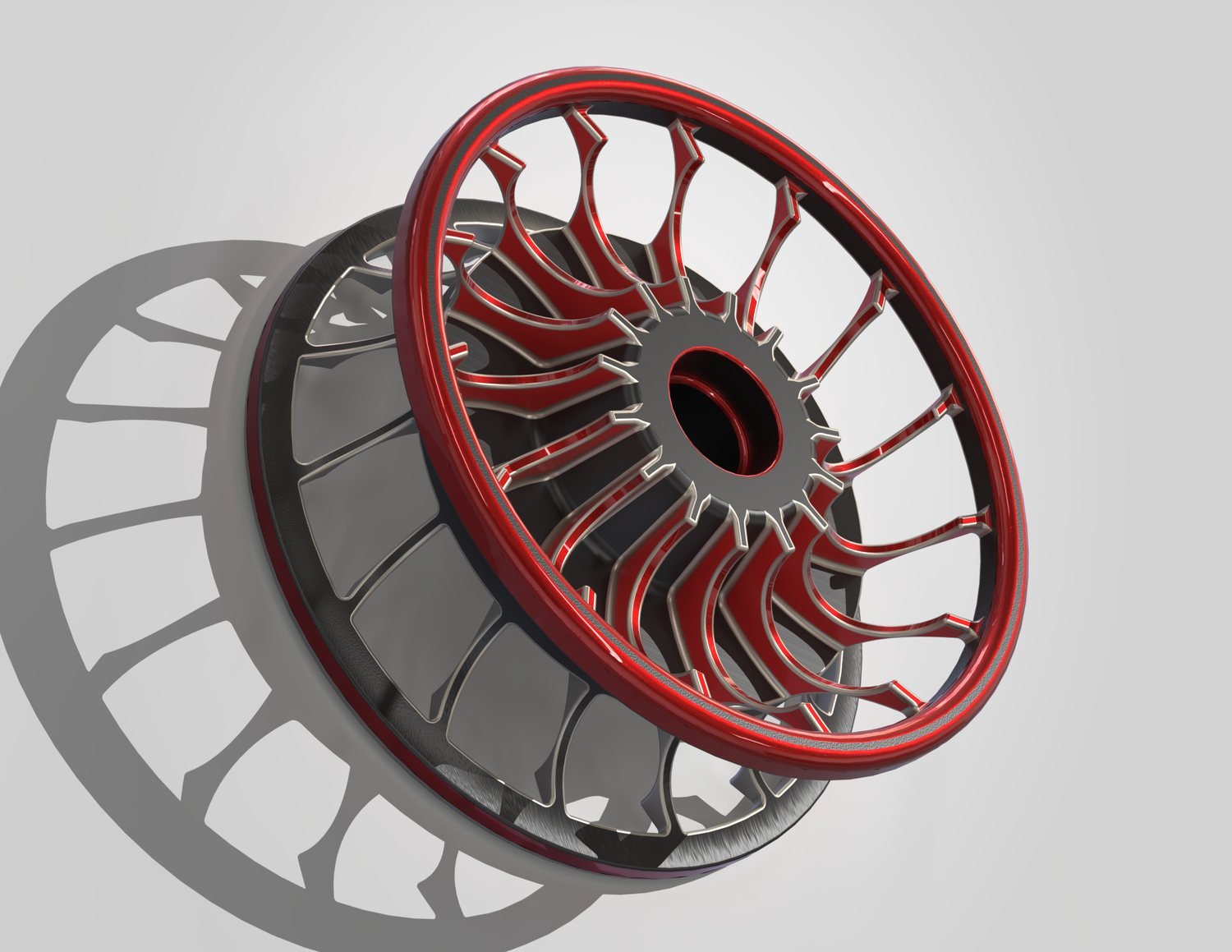
Custom Wheel: Revolve, Mirror & Circular Pattern
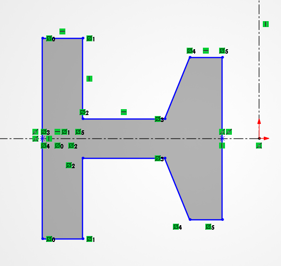
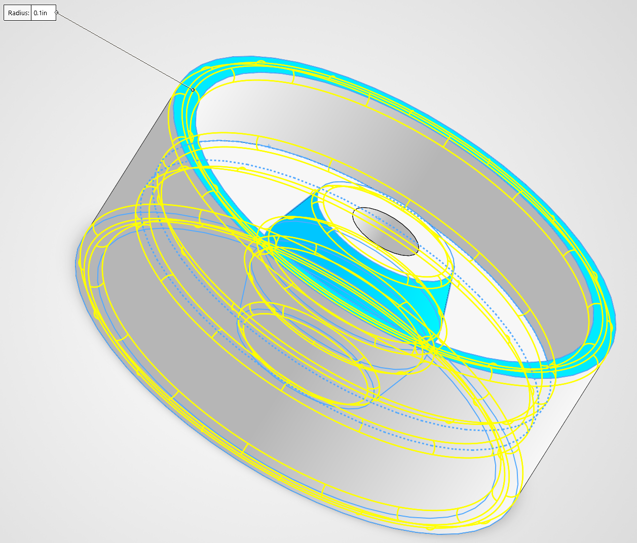
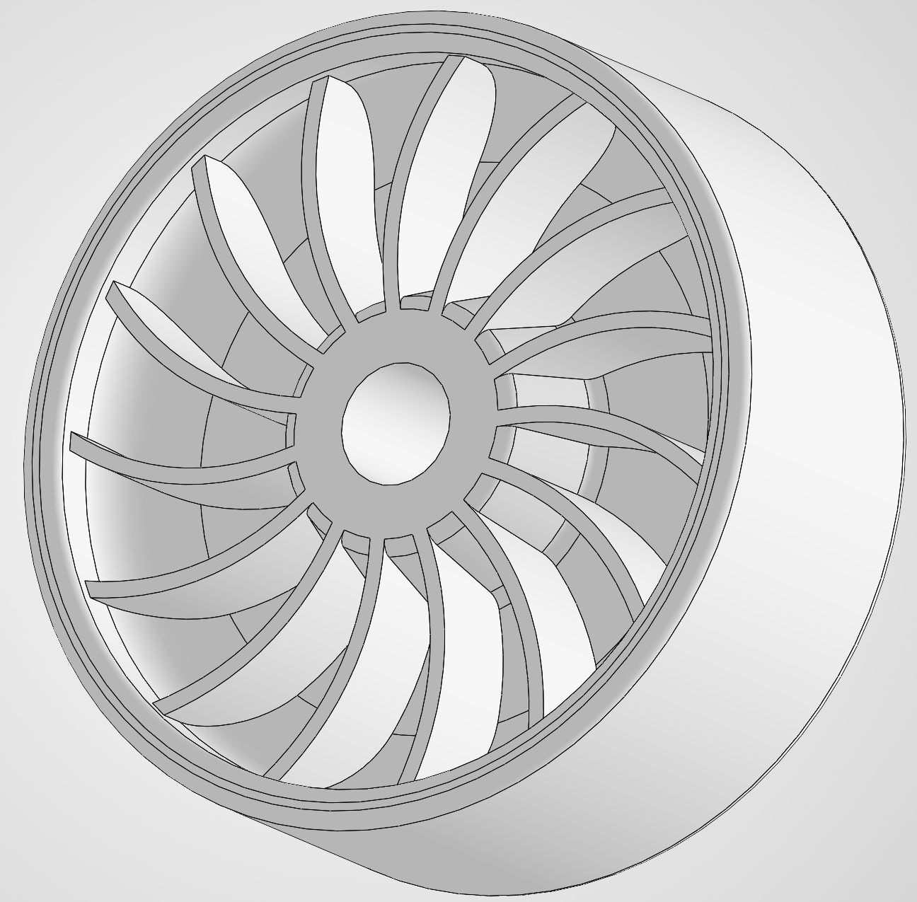
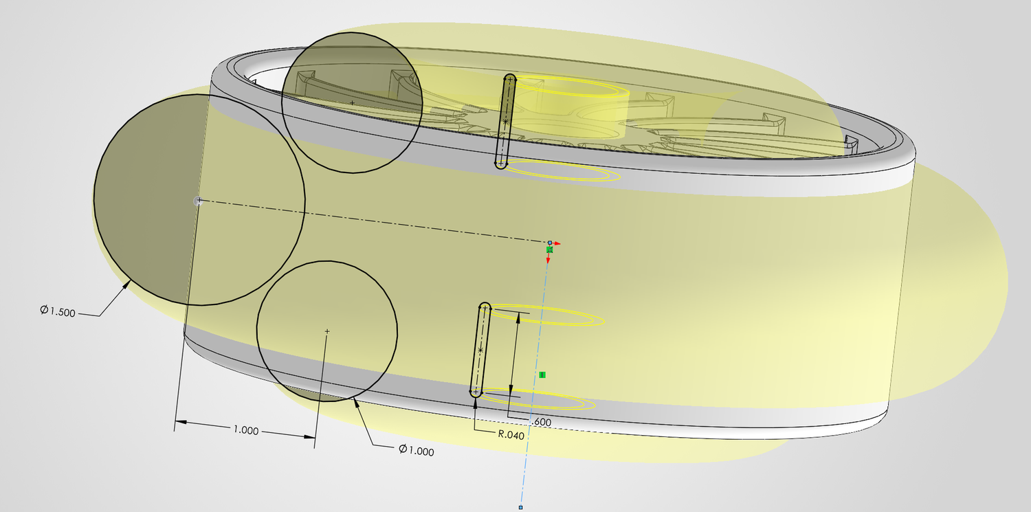
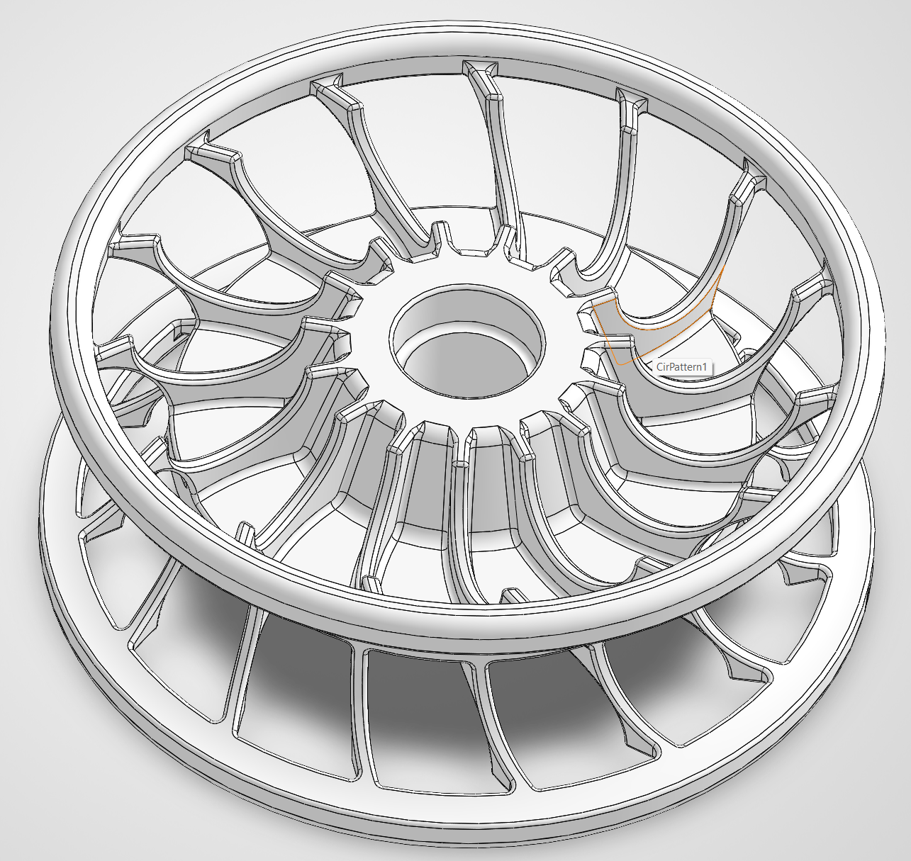
This was one of my larger projects. The base exercise teaches the revolve feature on a simple symmetric profile. I took it further into an original multi-spoke wheel design: a mirrored quarter-profile revolved into the rim, then a single curved spoke patterned around the hub with a circular pattern feature, finished with a two-tone chrome/red appearance to sell the render.
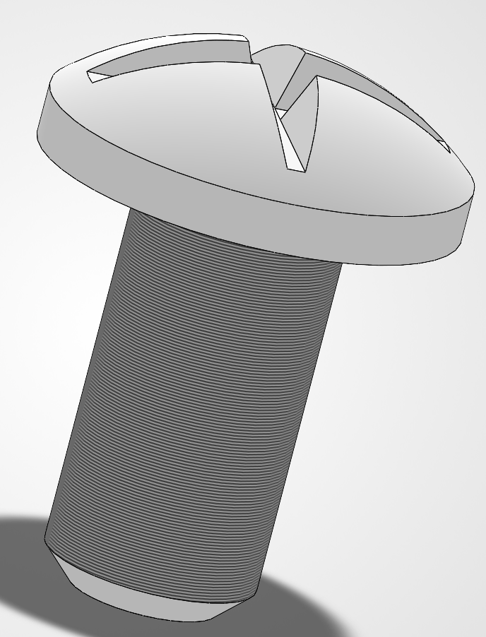
Fastener: Helical Thread Sweep & Phillips Drive Slot
A round-head screw built with a helix-and-sweep thread rather than a cosmetic thread — the thread profile actually follows a helical path cut into the shaft — plus a Phillips-style cross-slot cut into the domed head using projected sketch geometry.
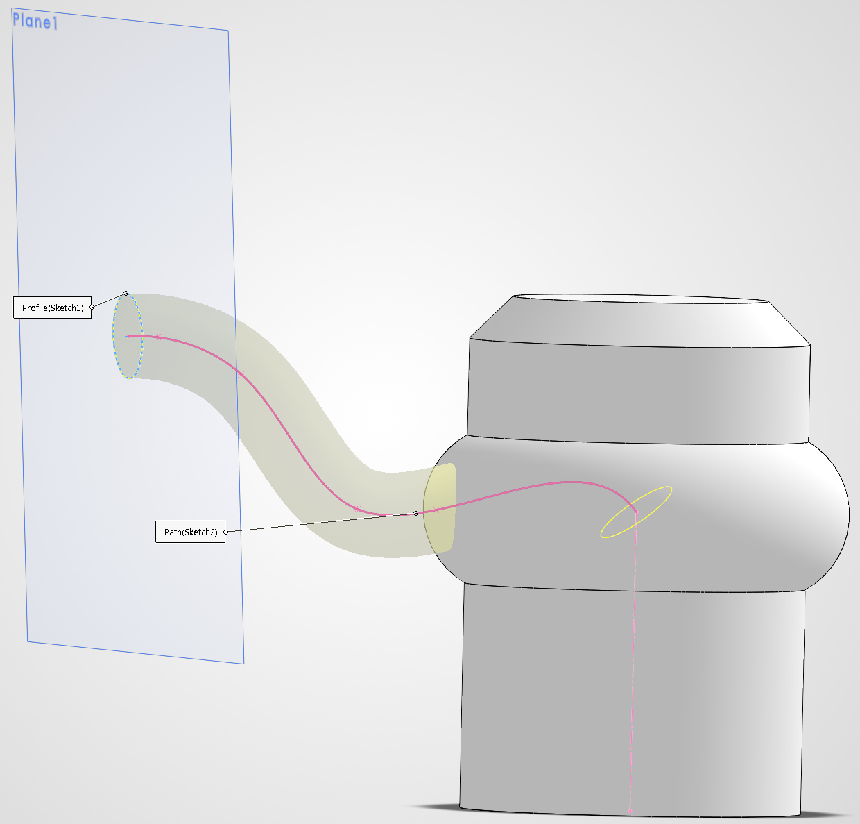
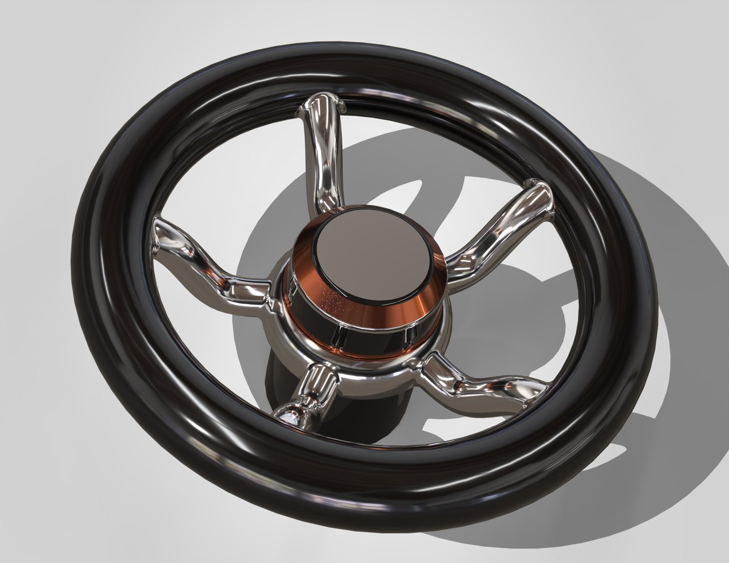
Handwheel: 3D-Sketch Spokes Swept Between Two Planes
A classic vintage-style handwheel: the rim and hub are revolved profiles, but each spoke is a true 3D sweep — a circular profile swept along a path sketched across two different reference planes so the spoke curves smoothly from the hub out to the rim instead of sitting flat in one plane. Finished in chrome and copper.
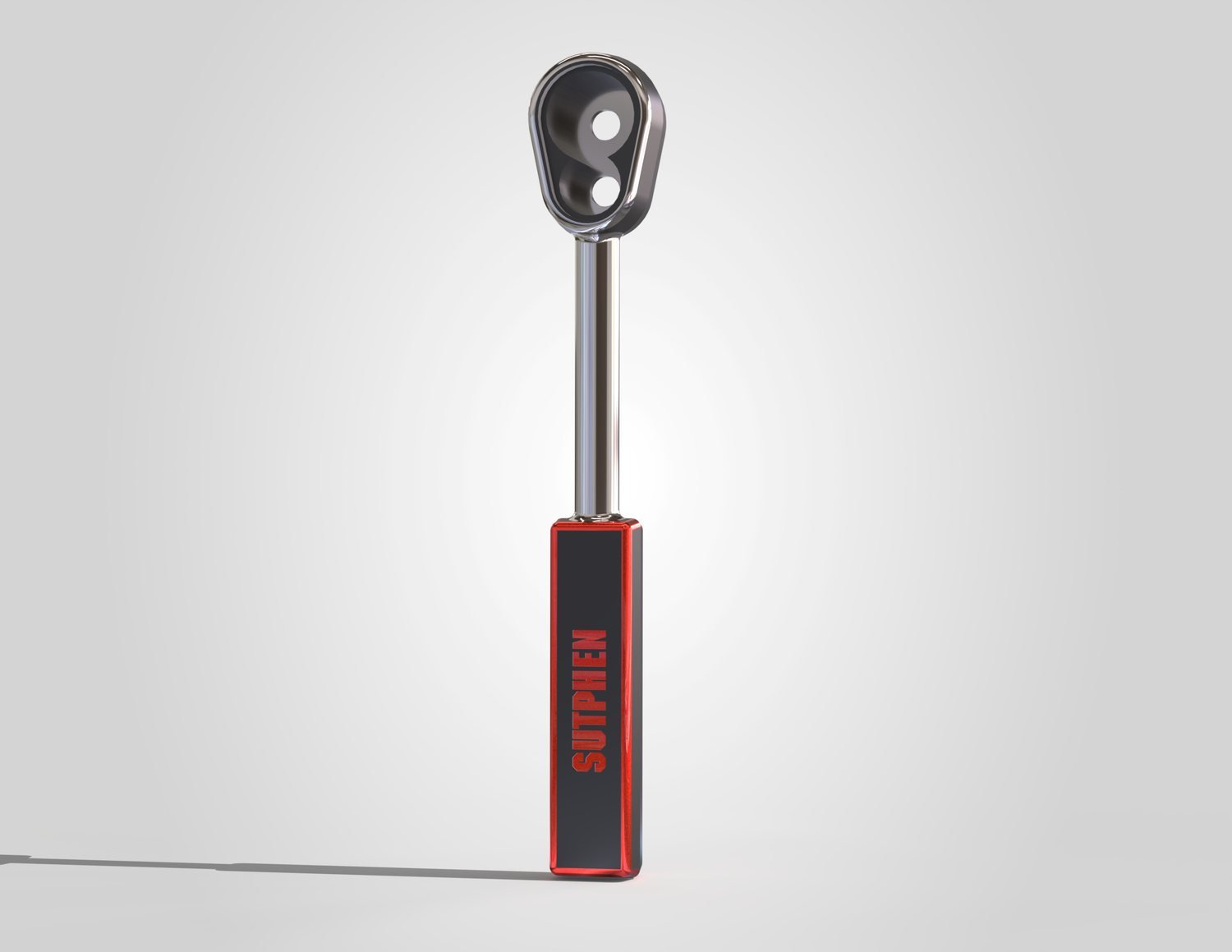
Sutphen Ratchet Tool: A Personal Design Built From Course Fundamentals
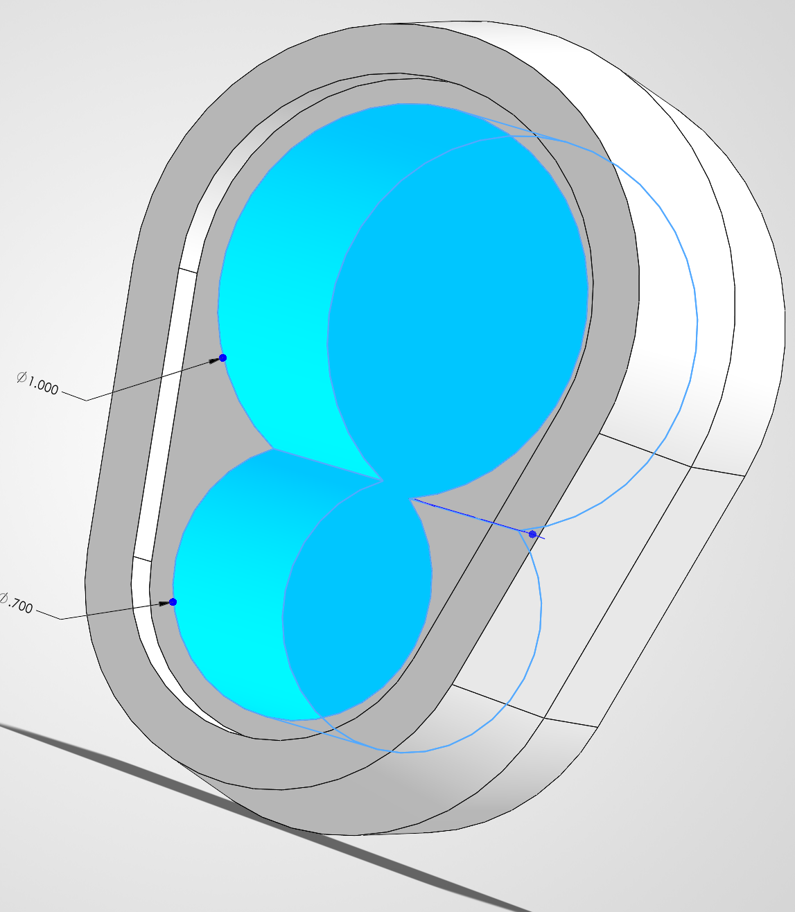
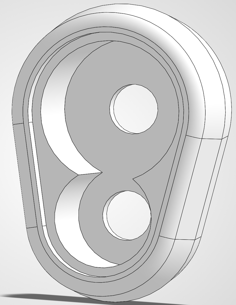
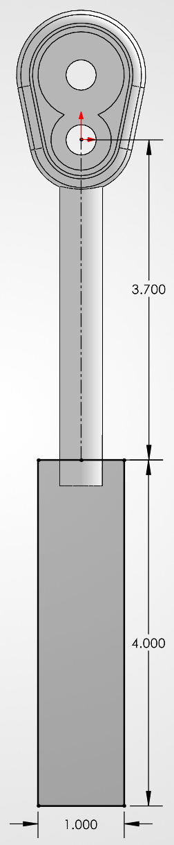
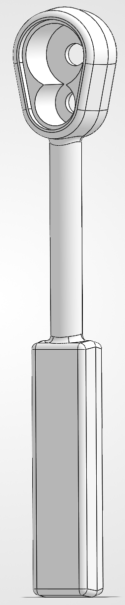
The most self-directed piece in the set: a full hand-tool design combining a decorative yin-yang-profile head with two bores, a round shaft, and a rectangular grip — all blended into one continuous part with fillets at every cross-section transition, branded for Sutphen.